
《德源科技》r)QTR-8RC 陣列循線感測器 數位輸出 Reflectance Sensor Array
$404
已售出 3 件
運費抵用券7-ELEVEN 滿99元運費折抵31元
- 現金付款
- 全家取貨付款
- 7-ELEVEN取貨付款
現金付款
- Yahoo奇摩輕鬆付現金接受付款方式:ATM轉帳 / Famiport / 輕鬆付帳戶餘額
ATM 提供5家銀行:合作金庫、華南銀行、台灣銀行、國泰世華、中國信託,以上5家同行轉帳,免轉帳手續費。
全家取貨付款
— Yahoo奇摩輕鬆付7-ELEVEN取貨付款
— Yahoo奇摩輕鬆付7-ELEVEN取貨付款 — 單件運費$60、滿10件或消費滿$20000免運費
- 單件運費$60
- 滿2件,運費$60
- 滿3件,運費$60
- 滿10件或消費滿$20000免運費
全家取貨付款 — 單件運費$60、滿10件或消費滿$20000免運費
- 單件運費$60
- 滿2件,運費$60
- 滿3件,運費$60
- 滿10件或消費滿$20000免運費
郵局掛號 — 單件運費$60、滿10件或消費滿$20000免運費
- 單件運費$60
- 滿2件,運費$60
- 滿3件,運費$60
- 滿10件或消費滿$20000免運費

輕鬆付提供價金保管,交易更安心!
商品資訊
下標前請注意: (請先打電話連絡或提問,請見賣方關於我中有聯絡方式)
1.可以開發票
(PS:如合併結帳多項產品或是加購附件及開發票者,使用全家取貨付款的,結標後請自行修改金額)
2.可面交,現貨供應
3.下標後請填寫下列資料
1.帳號:
2.購買物品名稱:(如有很多型號時請註明清楚,謝謝)
3.地址:
4.郵遞區號:
5.郵款金額:
6.姓名:
7.帳號後5碼:
8.連絡電話:
===================================================================
id=6340
※本產品原廠代理從國外進口,有些交期較長,下訂前請詢問!

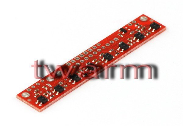
This sensor module has 8 IR LED/phototransistor pairs mounted on a 0.375" pitch, making it a great detector for a line-following robot. Pairs of LEDs are arranged in series to halve current consumption, and a MOSFET allows the LEDs to be turned off for additional sensing or power-savings options. Each sensor provides a separate digital I/O-measurable output.
RoboClaw 8RC陣列循線感測器擁有8個紅外線LED/光電晶體,非常適合用於循線機器人身上。成對的LED串聯減少電流消耗,MOSFET允許LED為增加敏感度或節省電力被關掉的選項。每個感測器都分別有數位I/O-測量的輸出。(有輸出值的大小,非 "0" 與 "1")
Note: The QTR-8RC reflectance sensor array requires digital I/O lines to take readings. The similar QTR-8A reflectance sensor array is available with analog outputs, and the reflectance sensor is available individually as a QTR-1RC reflectance sensor or QTR-1A reflectance sensor.
 |
Functional Description
The QTR-8RC reflectance sensor array is intended as a line sensor, but it can be used as a general-purpose proximity or reflectance sensor. The module is a convenient carrier for eight IR emitter and receiver (phototransistor) pairs evenly spaced at intervals of 0.375" (9.525 mm). Each phototransistor uses a capacitor discharge circuit that allows a digital I/O line on a microcontroller to take an analog reading of reflected IR by measuring the discharge time of the capacitor. Shorter capacitor discharge time is an indication of greater reflection.
The outputs are all independent, but the LEDs are arranged in pairs to halve current consumption. The LEDs are controlled by a MOSFET with a gate normally pulled high, allowing the LEDs to be turned off by setting the MOSFET gate to a low voltage. Turning the LEDs off might be advantageous for limiting power consumption when the sensors are not in use or for varying the effective brightness of the LEDs through PWM control.
The LED current-limiting resistors for 5 V operation are arranged in two stages; this allows a simple bypass of one stage to enable operation at 3.3 V. The LED current is approximately 20-25 mA, making the total board consumption just under 100 mA. The schematic diagram of the module is shown below:
 |
Specifications
- Dimensions: 2.95" x 0.5" x 0.125" (without header pins installed)
- Operating voltage: 3.3-5.0 V
- Supply current: 100 mA
- Output format: 8 digital pulse signals
- Optimal sensing distance: 0.125" (3 mm)
- Maximum recommended sensing distance: 0.375" (9.5 mm)
- Weight without header pins: 0.11 oz (3.09 g)
 |
| QTR-1RC output (yellow) when 1/8" above a black line and microcontroller timing of that output (blue). |
|---|
Interfacing the QTR-8RC Outputs to Digital I/O Lines
Like the Parallax QTI, the QTR-8RC module has eight identical sensor outputs that require a digital I/O line capable of first charging the output capacitor (by driving the line high) and then measuring the time for the capacitor to discharge through the phototransistor. This measurement approach has several advantages, especially when coupled with the ability of the QTR-8RC module to turn off LED power:
- No analog-to-digital converter (ADC) is required
- Improved sensitivity over voltage-divider analog output
- Parallel reading of all eight sensors is possible with most microcontrollers
- Parallel reading allows optimized use of LED power enable option
The typical sequence for reading a sensor is:
- Turn on IR LEDs (optional)
- Set the I/O line to an output and drive it high
- Allow at least 10 us for the 10 nF capacitor to charge
- Make the I/O line an input (high impedance)
- Measure the time for the capacitor to discharge by waiting for the I/O line to go low
- Turn off IR LEDs (optional)
These steps can typically be executed in parallel on multiple I/O lines.
With a strong reflectance, the discharge time can be as low as several dozen microseconds; with no reflectance, the discharge time can be up to a few milliseconds. The exact time of the discharge depends on your microcontroller’s I/O line characteristics. Meaningful results can be available within 1 ms in typical cases (i.e. when not trying to measure subtle differences in low-reflectance scenarios), allowing up to 1 kHz sampling of all 8 sensors. If lower-frequency sampling is sufficient, substantial power savings can be realized by turning off the LEDs. For example, if a 100 Hz sampling rate is acceptable, the LEDs can be off 90% of the time, lowering average current consumption from 100 mA to 10 mA.
Our Pololu AVR library provides functions that make it easy to use these sensors with our Orangutan robot controllers; please see the QTR Reflectance Sensors section of our library command reference for more information. We also have a Arduino library for these sensors.
Breaking the Module in Two
If you don’t need or cannot fit all eight sensors, you can break off two sensors and still use all 8 sensors as two separate modules, as shown below. The PCB can be scored from both sides along the perforation and then bent until it snaps apart. Each of the two resulting pieces will function as an independent line sensor.
 |
Included Components
This module ships with a 25-pin 0.1" header strip and a 100 Ohm through-hole resistor as shown below.
 |
You can break the header strip into smaller pieces and solder them onto your reflectance sensor array as desired, or you can solder wires directly to the unit or use a right-angle header strip for a more compact installation. The pins on the module are arranged so that they can all be accessed using either an 11×1 strip or an 8×2 strip.
The resistor is required to make the two-sensor array functional after the original eight-sensor array is broken into two pieces. This resistor is only needed once the board has been broken.
 |
| Solder the included resistor to the 2-sensor array piece as shown to make the separated piece functional. |
|---|
